

1. Scope
The specification includes Normal Diameter NPS 10~NPS48, Normal Pressure Class (150LB~300LB) flanged triple eccentric metal seal butterfly valves.
2. Product Description
2.1 Technical requirements
2.1.1 Design and Manufacture standard:API 609
2.1.2 End to end connection standard:ASME B16.5
2.1.3 Face to face dimension standard:API609
2.1.4 The pressure-temperature grade standard:ASME B16.34
2.1.5 Inspection and test (including hydraulic test): API 598
2.2 Product General
The triple eccentric butterfly valve with double metal sealing is one of BVMC's major products, and widely used in metallurgy, light industry, electric power, petrochemical, gas channel and other fields.
3. Characteristics and Application
The structure is triple eccentric and metal seated. It has good sealing performance under the condition of room temperature and/or high temperature. Smaller volume, lighter weight, opening and closing flexibly and longer working life are its obvious advantages compared to gate valves or globe valves. It is widely used in metallurgy, light industry, electric power, petrochemical, coal gas channel and other fields, the use of safety reliable, the valve is the optimal choice of modern enterprises.
4.Structure
4.1 Triple eccentric metal sealing butterfly valve as shown in Sketch 1
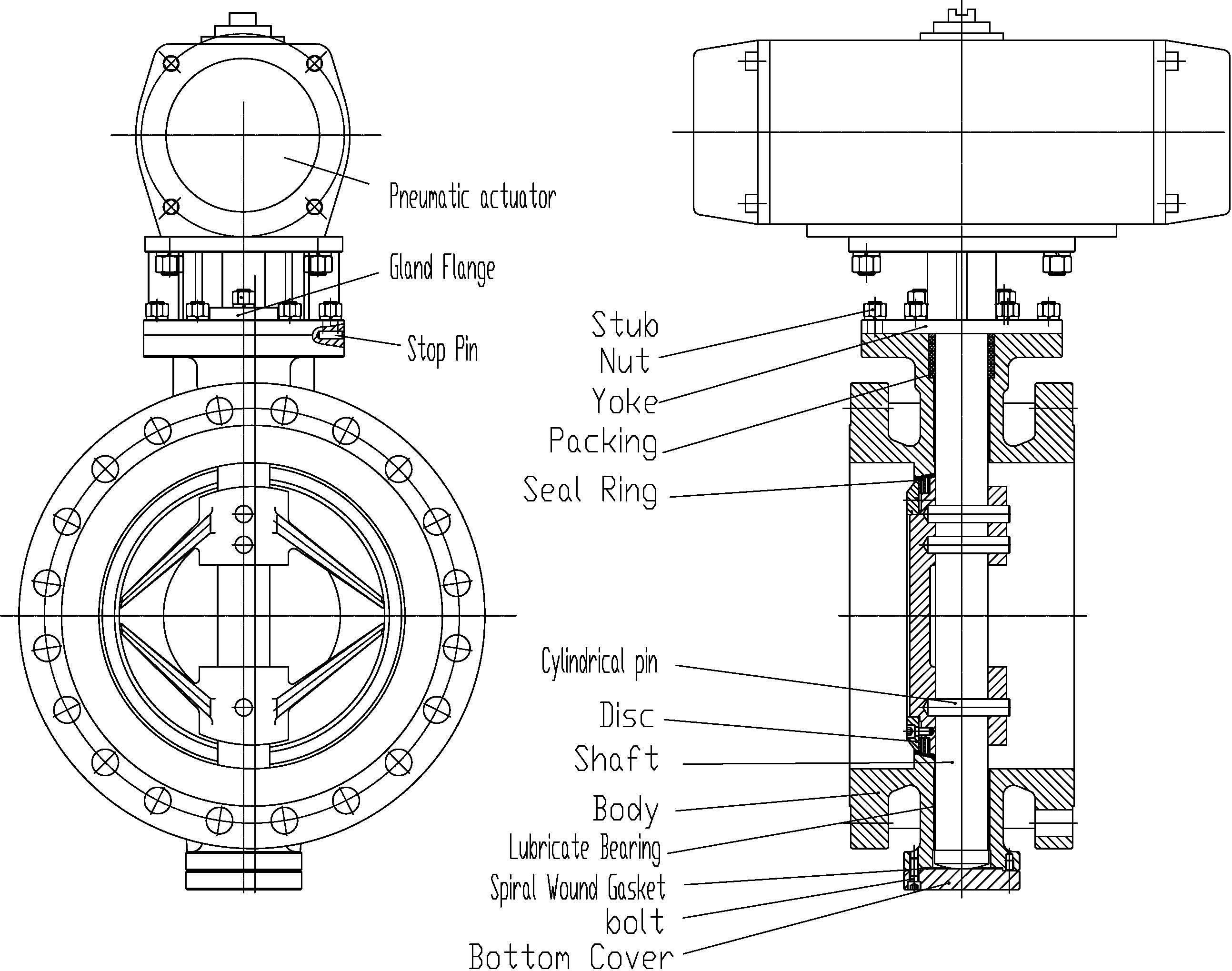
Figure 1 Triple eccentric metal sealing butterfly valve
5. The sealing principle:
Figure 2 A typical triple eccentric metal sealing butterfly valve is a typical BVMC product, as shown in sketch 2.
(a) Structure Characteristics: The rotation center of the butterfly plate (i.e. valve center) is to form a bias A with the butterfly plate sealing surface, and a bias B with the center line of the valve body. And an Angle βbe created between the center line of the seal face and seat body (i.e., the axial line of the body)
(b) Principle of sealing: Based on the double eccentric butterfly valve , the triple eccentric butterfly valve developed an Angleβ between the centerlines of the seat and the body. The bias effect is as shown in figure 3 cross-section. When triple eccentric sealing butterfly valve is in fully open position, the butterfly plate sealing surface will be completely separated from the valve seat sealing surface. And there will form clearance γbetween the butterfly plate sealing face and body sealing surface as same as double eccentric butterfly valve. As shown in figure 4, due to the formation of β angle , anglesβ1and β2 will form between the tangent line of disc rotation track and the valve seat sealing surface. When opening and closing disc, the butterfly plate sealing surface will gradually separate and compact, and then completely eliminate mechanical wear and abrasion. When break open the valve, the disc sealing surface will separate instantly from the valve seat. And only at the fully closed moment, the disc will compact into the seat. As shown in figure4, due to the formation of angle β1and β2 , when the butterfly valve is closed, the seal pressure be produced by valve shaft drive torque generation not flexibility of butterfly valve seat. It can not only eliminate the possibility of seal effect reduction and failure caused by seat material aging, cold flow, elastic invalidation factors, and can be freely adjusted through drive torque, so that the triple eccentric butterfly valve sealing performance and working life will be greatly improved.
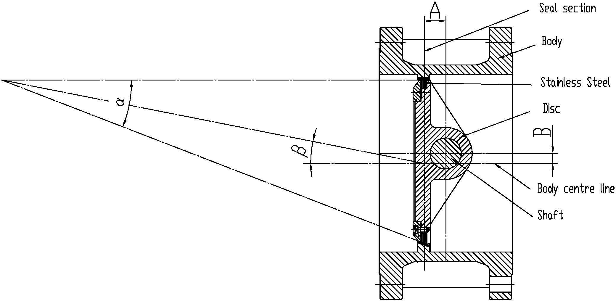
Figure 2 Triple eccentric double-way metal sealed butterfly valve
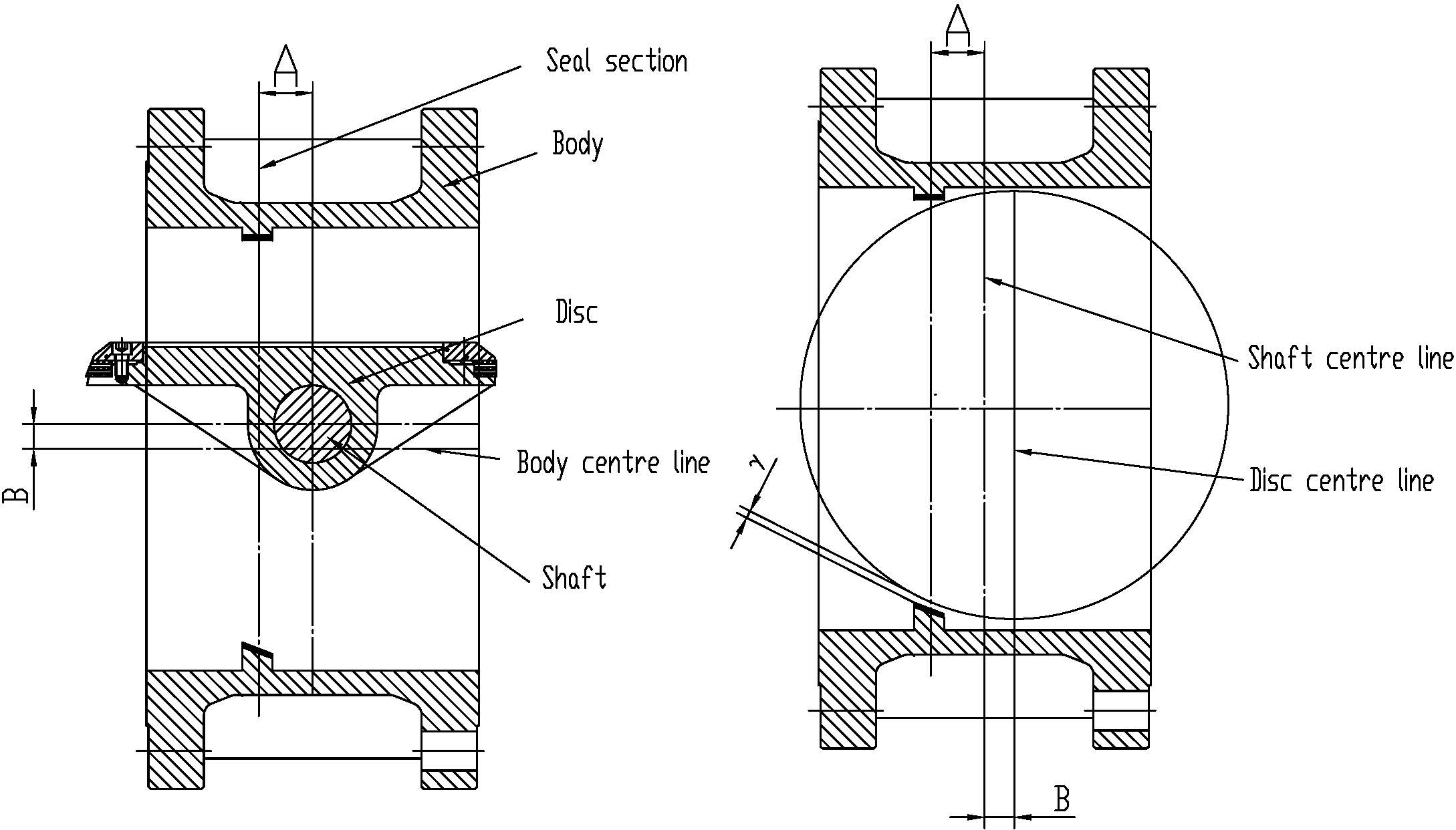
Figure 3 Diagram for triple eccentric double metal sealing butterfly valve at open state
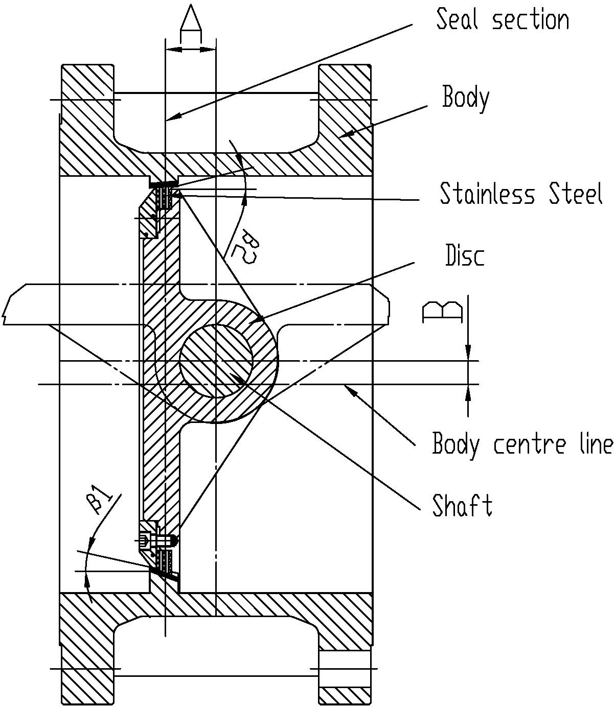
Figure 4 Diagram for triple eccentric double metal sealing butterfly valve at close state
6.1 Installation
6.1.1 Checking carefully the contents of valve nameplate before installing , ensure that type, size, seat material and temperature of the valve will be in accordance with the service of pipeline.
6.1.2 Checking preferably all bolts in connections before installation, making sure it’s tightening evenly. And checking whether compression and sealing of packing.
6.1.3 Checking valve with flow marks, such as indicates the direction of flow,
And installing the valve should be in accordance with the provisions of the flow.
6.1.4 The pipeline should be cleaned and removed its oils, welding slag and other impurities before installation.
6.1.5 Valve should be taken out gently, prohibiting its throwing and dropping.
6.1.6 We should remove the dust cover at the ends of the valve when installing the valve.
6.1.7 When installing the valve, the thickness for flange gasket is more than 2 mm and shore hardness is more than 70 PTFE or winding gasket, flange of the connecting bolts should be tighten diagonally.
6.1.8 The looseness of packing may be caused by change of vibration and temperature in transportation, and tightening nuts of the packing gland if there is leakage in the stem sealing after installation.
6.1.9 Before installing the valve, the location of pneumatic actuator must be set up, in order to artificial operation and maintenance under unexpected. And the actuator must be checked and tested before putting into the production.
6.1.10 The incoming inspection should be according to relevant standards. If the method is not correct or man-made caused, BVMC Company will not take any responsibility.
6.2 Storage and Maintenance
6.2.1 The ends should be covered with dust cover in dry and ventilated room, to ensure pureness of valve cavity.
6.2.2 When valve for the long-term storage is reused, the packing should be checked whether it is invalid and fill lubricant oil into the rotating parts.
6.2.3 The valves must be used and maintained in the warranty period (according to the contract), including replacement of gasket, packing etc.
6.2.4 The working conditions of valve must keep clean, because it can extend its service life.
6.2.5 Valves need to inspect and maintenance regularly in operating to protect from corrosion resistance and ensure that the equipment is in ok condition.
If the medium is water or oil, it is suggested that valves should be checked and maintained every three months. And if the medium is corrosive, it is suggested that all the valves or part of valves should be checked and maintained every month.
6.2.6 Air filter relief-pressure valve should drain regularly, pollution discharge, replace the filter element. Keeping the air clean and dry to avoid pollution pneumatic components, cause of failure. (Seeing "the pneumatic actuator operation instruction")
6.2.7 Cylinder, pneumatic components and piping should be checked carefully and regularly to prohibit gas leakage (Seeing "the pneumatic actuator operation instruction")
6.2.8 When repairing the valves shall flush the parts again, removal foreign body, stains and rusty spot. To replace the damaged gaskets and packing, sealing surface should be fixed. Hydraulic test should be carried out again after repairing, qualified can use.
6.2.9 Activity part of the valve (such as stem and packing seal) must keep clean and wipe out the dust to protect from fray and corrosion.
6.2.10 If there is leakage in the packing and the packing gland nuts should be tightened directly or change the packing according to the situation. But It is not allowed to change the packing with pressure.
6.2.11 If the valve leakage is not solved online or for other operating problems, when remove the valve should be according to the following steps:
a.Pay attention to safety: for your safety, removing the valve from the pipe first should understand what the medium in the pipeline is. You should wear the labor protection equipment to prevent the medium inside the pipeline damage. At the same time to ensure that the pipeline medium pressure already. The valve should be fully closed before removing the valve.
b.Removing the pneumatic device (including the connect sleeve, Seeing "the pneumatic actuator operation instruction") should be careful to operate in order to avoid damage from the stem and pneumatic device;
c.The sealing ring of disc and seat should be checked if they have any scratch when butterfly valve is open. If there is a slight scrape for seat, it can use emery cloth or oil on sealing surface for modification. If a few deep scratch appears, the appropriate measures should be taken to repair, the butterfly valve can use after test qualified.
d.If the stem packing is leakage, the packing gland should remove, and checking the stem and packing with the surface, if stem has any scratch, the valve should assemble after repairing. if packing is damaged ,the packing must be replaced.
e.If cylinder has problems, shall check the pneumatic components, ensure that gas path flow and air pressure, electromagnetic reversing valve is normal. Seeing "the pneumatic actuator operation instruction")
f.When the gas put into the pneumatic device, it makes sure that the cylinder no inside and outside has no leakage. If pneumatic device seal is damaged can lead to decreased operation pressure torque, so that not meet butterfly valve opening and closing operation, shall pay attention to regular inspection and replacement parts.
Pneumatic butterfly valve other parts generally does not repair. If the damage is serious, should contact the factory or send to factory maintenance.
6.2.12 Test
The valve shall be pressure test after the valve repaired the test in accordance with the relevant standards.
6.3 Operating instruction
6.3.1 Pneumatic operated valve with cylinder device driver will be made the disc rotated 90° to open or close the valve.
6.3.2 The open-close directions of pneumatic actuated butterfly valve shall be marked by position indicator on the pneumatic device.
6.3.3 Butterfly valve with truncation and adjust action can be used as a fluid switch and flow control. It generally not allowed beyond the pressure - temperature boundary condition or frequent alternating pressure and temperature conditions
6.3.4 Butterfly valve has the ability of resistance to high pressure difference, do not let the butterfly valve opened under high-pressure difference even at high pressure differential continues to circulate. Otherwise may cause damage, or even serious safety accident and property loss.
6.3.5 The pneumatic valves use frequently, and the movement performance and lubrication conditions should be checked regularly.
6.3.6 Pneumatic device clockwise for butterfly valve to closed, counterclockwise for butterfly valve to open.
6.3.7 Using the pneumatic butterfly valve must pay attention to the air is clean, the air supply pressure is 0.4 ~ 0.7 Mpa. To maintain air passages open, not allowed to block air inlet and air flow. Before working, it needs to enter into the compressed air to observe if the pneumatic butterfly valve movement is normal. pay attention to the pneumatic butterfly valve open or closed, whether disc is in full open or closed position. To pay attention to the position of the valve and the cylinder position is consistent.
6.3.8 The structure of pneumatic actuators crank arm is rectangular head, used for manual device. When the accident occurs, it can remove the air supply pipe directly with a wrench that the manual operation can be realized.
7. Mistakes, reasons and solution (See Tab 1)
Tab 1 Possible problems, causes and solution
|
Mistakes |
Cause of failure |
Solution |
|
The valve moving for valves is difficult, not flexible |
1. Actuator failures2. Open the torque is too big3. Air pressure is too low
4.Cylinder leakage |
1. Repair and check the electric circuit and gas circuit for pneumatic device2.Reducing the loading of work and choosing pneumatic devices correctly3.Heighten air pressure
4. Check the sealing conditions for cylinder or source of joint |
| Stem Packing Leakage | 1. Packing gland bolts is loose2. Damage packing or stem | 1. Tighten gland bolts2. Replace the packing or stem |
| Leakage | 1.The closing position for the deputy of sealing is not correct | 1. Adjusting the actuator to make the closing position for the deputy of sealing is correct |
| 2. Closing does not reach the designated position | 1.Checking the direction of open-close is in place2.Adjusting according with actuator specifications, so that the direction is synchronized with the state of the actual open3. Checking the catching objects is in the pipeline | |
| 3. Parts of valve damage① Seat damage② Disc damage | 1. Replace seat2. Replace disc | |
|
Actuator lapse |
1.The key damage and drop2.The stop pin cut off | 1. Replace the key between the stem and the actuator2. Replace the stop pin |
|
The pneumatic device failure |
Seeing "valve pneumatic device specifications" |
|
Note: Maintenance personnel shall have relevant knowledge and experience.
Post time: May-19-2022